Body-Powered Trikke Physics
Draft: 23 November 2022
At first sight a body-powered Trikke appears to possess no mechanism to propel it. No pedals, gears, chains or motion transduction equipment. Three ingeniously connected tubes form two trailing arms terminated over wheels and a tall steering column, called the "stem", articulate at the "yoke" to camber all three wheels at once. The caster-mounted wheel beneath the stem guides the vehicle under power of the rider's motive gyrations. Riders grip the stem handlebars standing with feet on their respective arm decks. Four levers lay hidden among this conceptually simple geometry setting three mechanisms in motion that power the Trikke. First principles guide this study of Trikke locomotion through the derivation of mathematical models for these motion-producing mechanisms. Simple physics shows how riders' angular momentum cranks a virtual class II lever that forms inside a turn to one side, then flips to the other while steering the Trikke's signature sinusoidal path. This provides two opportunities to drive forward every cycle. A turntable on a spinning base best summarizes the mechanism. Drawing it all together, a "simple" equation of motion and two concept demonstration "toys" complete the analysis. These models of local dynamics highlight the Trikke's synergistic design to understand what makes a Trikke move.
Trikke Levers and Mechanisms of Motion
Trikkes coast when not turning. To ride a Trikke is to constantly swivel the handlebars from one side to the other while coordinating the various activities that provide power to the system. Mechanisms that drive mechanical propulsion generally boil down to actions that move levers and push or pull rods. Levers, gears (which are notched, curved levers) and wheels all rotate. There are very few of these elements on a Trikke and fewer linkages between them. Some of the linkages identified are real. Others arise from real system components, like the road, in more conceptual ways.
Two primary types of actions, linear and rotational, propagate motion through mechanical systems. System analysts may describe these actions using "generalized coordinates" that guide forces and torques that shape and obey Equations of Motion, their dynamics and constraints. Solving these equations for energies, local accelerations, velocities, positions of parts, performance envelopes and global kinematics provide a deep understanding only visible in the details. This approach works best when the local dynamics lead seamlessly to global kinematics.
However, the simple mechanics of a Trikke provide formidable obstacles to such an approach, including being a nonholonomic system. Setting aside that machinery, this first principles study derives the local dynamics largely from momentum conservation. As the masses of Trikke components don't change significantly, the word "action" used below often means "momentum" or "velocity" rather than "energy" or "force" and "torque". The goal here is not to provide a global solution for the kinematics by solving equations of motion, but to elucidate the local dynamics that more scholarly approaches like [RoboTrikke] did not.
Organization: This report includes general terminology needed throughout, followed by an introduction of the moving-part "actors". Levers are illustrated and the mechanisms they animate are briefly described at an "executive" level. Physical concepts and some vector analysis required to understand and represent the mechanisms more precisely follow for the benefit of motivated readers. Conceptual derivations of the mechanism models provide the main body of the paper. Most of the interesting and useful insights are in these sections. I tried to make them accessible at some level to readers without a great amount of familiarity with physics or analysis. After conclusions, the appendices contain mathematical proofs, useful physical concepts and more detailed derivations of the physics models. The results of this analysis have been implemented in a forward-feed, discrete, [calibrated] Trikke/Rider [simulation] demonstrating typical Trikke [behaviors] that provide a basis for Trikke [magic].
Four Levers
Levers identified in mechanical systems are of three classes based on how their fulcrum, load and action are placed. "Linkages" connect their fulcrums, loads and actions. They can be physical levers minimally shaped like rods or irregular shapes bearing little resemblance to a rod without a line of material passing through its elements; in a sense "virtual".
One of the four levers involves the physical structure of the steering column with linkages extending from the guide-wheel's contact point to the handlebars. This Camber-Lever is a second-class lever with large mechanical advantage that makes moving the handlebars from side-to-side easy.
The most important lever is not physical in the same sense. Anchored at the instantaneous turn-center and extending to the guide-wheel contact point, the Turn-Lever "virtual" lever pulls the entire Trikke around. The physical linkages to the load of this lever are realized in the structure of the Trikke and extend to the road by the constraints of friction on all three wheels. It is also the longest lever, stretching almost to infinity.
Two more levers operate in tandem to rotate, pull and push the trailer into, toward and away from the guide-wheel contact. One is degenerate with action at the intersection of all three tubes, the yoke. This Yoke-Lever, has its fulcrum at the guide-wheel contact with load and action at the yoke. Its mate, the Trailer-Lever, extends from its action at the yoke, to the instantaneous transom point. Mostly, it rotates its load - the center of mass of the trailer.
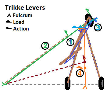
Figure 4 below illustrates the four Trikke levers. Movement of the dark brown dot, the TRS center of mass, is the goal of these levers. It is constrained to move in the direction of the dark brown ray. Along the way, the trailer's center of mass (orange dot) may also move.
- Camber-Lever: As the rider steers and cambers a Trikke, the guide-wheel's contact point (green dot under guide-wheel in Figure 4) forms a fulcrum (blue ^) for the handlebar action (blue double-ray) through the Camber-Lever (blue line near circumscribed '1'). The yoke is the load (blue load). It is a second-class lever. Cambering can move the yoke side-to-side a couple decimeters. Because of the castered guide-wheel's negative rake, merely turning the stem also moves the yoke in orbit around the contact point. Yoke movement is the action behind "Castering" a Trikke. When the guide-wheel cambers, the rear-wheels camber with it to very near the same angle. They are permanently cambered about -5°; bottom further out than top.
- Turn-Lever: Nothing happens in Trikke locomotion without involving this lever (green line near circumscribed '2'). When the stem is set to a particular turn angle, θ, lines (dashed-gray and solid-green) extended through each axle of the three wheels intersect at a point called the turn-center. As the name implies, a Trikke orbits this point at this turn-radius (green line), as long as the turn angle doesn't change. However, the turn angle constantly changes, so technically, the green line is the "instantaneous guide-wheel contact turn-ray". The turn-center is the fulcrum (green ^). Action occurs at the guide-wheel contact point (green patch under wheel with green ray). The TRS center of mass is the load acted on (displaced light brown dashed-line on the Turn-Lever). It can be a second or third-class lever.
- Yoke-Lever: Extending from its stem contact fulcrum (light blue ^ under wheel) to the yoke, this degenerate lever (light blue line near circumscribed '3') rotates around the Camber-Lever. Due to the rotation, it acts (light blue ray) on the yoke, which is also its load (light blue load). It constitutes one of two levers involved with the castering mechanism.
- Trailer-Lever: The trailer along with this lever (orange line near circumscribed '4') constitutes the second part of the castering mechanism. Action (orange ray) rotates, pushes and pulls this lever at the yoke. It is anchored at a transom fulcrum (orange ^) which causes it to move its load, the trailer's center of mass. It is a second-class lever and push-rod. The trailer includes the Trikke arms with their wheels and the rider minus body parts that are kinetically part of the handlebars - like hands and wrists. The trailer can be thought of as a distribution of sub-masses with two road contact points.
Three Mechanisms
Three mechanisms Jetting, Carving and Castering combine synergistically via the four levers to propel three-wheeled, body-powered Trikke riders' fun. Trikke locomotion is characterized by the serpentine track carved mostly side-to-side across a road as the rider coordinates steering, cambering and carving. These mechanisms allow riders to conjure the forces to snake out speeds over 4.5 meters per second on a level road. Note that "carving" includes "jetting", but jetting is the most fundamental mechanism of Trikke locomotion, so it is often mentioned outside of the carving context.
- Carving Mechanisms
Jetting, Direct-Push and Direct-Pull are the carving mechanisms driven by two of the four Trikke levers. Jetting is the simplest, employing the virtual Turn-Lever. When activating any of these mechanisms, the rider produces an action at the guide-wheel contact point through rotation. The fulcrum of the Turn-Lever pivots on the turn-center causing the TRS center of mass, the load, to orbit the turn-center. Jetting pries the Turn-Lever like a crowbar dislodging a stone. Constrained to orbit and being solidly connected to the stem via human legs and metal bars, the TRS center of mass must move with the rotation of the lever.
- Jetting: This term comes from an old skiing technique used until the mid 1980's when ski materials improved dramatically. It involved shoving both feet forward to top small ridges or up-sloping turns. Dropping one's center of mass to power the jet made it difficult to maintain balance.
Trikkes are much more stable and the jet is mainly performed one foot at a time - a hemijet. The physical goal of hemijetting (or just jetting) a Trikke is to accelerate the rotation of the outside arm around the Turn-Ray Lever into the guide-wheel path. When the guide-wheel accelerates, every part of the Trikke is compelled to accelerate with it in proportion to its turn-radius ratio. A part further from the turn-center than the stem orbits faster than the stem. The inside wheel orbits the slowest because it is closest to the turn-center. Model-wise, the guide-wheel pushes the Turn-Ray Lever which pulls the TRS center of mass around the turn-center. This is a consequence of the constraints provided by friction on the wheels.
Unlike linear actions, jetting does not require the rider to "reset" center of mass position; the action is generated without moving the rider's local center of mass. There is NO recoil. When led by a hip twist and a delayed turn to the same side, the rider's angular momentum is first reflected then transferred to the Trikke-Rider pair as co-rotation via The Law of Conservation of Angular Momentum. Pure jetting is a ROTATION. Each of the other mechanisms describe how linear actions between Trikke components also synergistically feed into a jet rotation. A Trikke CANNOT move backward when the rider jets forward, unless slipping down a steep hill. A simple system that embodies momentum transfer through rotation is a turntable on a spinning platform.
However, when turning to the left, jetting by rotating the left side of the body around to the front opposes the turn and reflects the jet into acceleration. The construction of the Trikke makes this difficult to perform from a stop so that a casual rider attempting it as an experiment does not experience much acceleration at all. Some riders may experience this differently and "wind up" before and during a turn, building bodily rotation but not releasing it to the Trikke, like caster does.
- Direct-Push and Pull
Direct Push-Pull mechanisms feed into jetting, but lose some momentum in the process.
- Push: Assuming a Trikke is steered straight ahead, pushing it forward by recoiling the rider backward does not change the TRS center of mass location. The center of mass is stationary throughout the motion. However, the rider and Trikke centers of mass do shift position in opposite directions to conserve momentum.
Constrained on an arch as a Trikke turns, the pushing rider and pushed Extended-Trikke agents generally have different turn-radii. When this is the case, conservation of angular momentum demands that a rider's push cause the TRS system center to move! However, the motion stops when the push stops. Never-the-less, the TRS center of mass takes a "step". During the step, a velocity manifests that is proportional to the ratio of the agents' moments of inertia and the ratio of Turn-Lever length to the TRS turn-radius. Motion ends as the rider and Extended-Trikke continue together as one unit in a perfectly inelastic collision. In the detailed derivation, this angular process is treated linearly via components at the guide-wheel contact point. Never-the-less, the Push orbital component becomes the jet and its radial component grounds into Earth's momentum via friction across the wheels. Angular and linear momentum are conserved.
- Pull: Pull is the opposite of Push. TRS center of mass location is stationary in a no-turn, linear pull. But like the direct-push constrained on an arch, the TRS center of mass is also not stationary. It takes a "step", but in the opposite (wrong) direction. Again, it originates from the conservation of angular momentum, while it ends in a perfectly inelastic collision. Opposite a push, a backward jetting rotation occurs via the Turn-Lever to motivate the step while the pull is in effect. The beauty of Trikke dynamics, one of many synergies, is that a push and turn to one side resets the rider's center of mass for a push and turn to the other side without needing a strong reset pull! It becomes a weak impulse, or better, no impulse.
- Push: Assuming a Trikke is steered straight ahead, pushing it forward by recoiling the rider backward does not change the TRS center of mass location. The center of mass is stationary throughout the motion. However, the rider and Trikke centers of mass do shift position in opposite directions to conserve momentum.
- Jetting: This term comes from an old skiing technique used until the mid 1980's when ski materials improved dramatically. It involved shoving both feet forward to top small ridges or up-sloping turns. Dropping one's center of mass to power the jet made it difficult to maintain balance.
- Caster Mechanism
A couple of studies have concluded that a Trikke is propelled forward simply by cyclical steering; see [RoboTrikke] and [Roller Racer]. Personal experience shows this is a weak form of locomotion, especially starting from a stop. Note, it is very difficult to perform this task "pure castering" without throwing weight around or knowing for sure that the ground is level. Off you go when unintended jetting or downslope kicks in! When controlled to allow only castering (no cambering, extra jetting or slope) the guide-wheel contact point grinds in place. To emphasize caster-only locomotion, a rider must plant feet in front of the decks on the arm-bars close to the yoke. That moves the rider's center of mass forward enough to be demonstrably thrown into the turn by the Trailer-Lever; generating a decent jet. In normal practice, the rider is too far back to produce a caster-jet strong enough to initiate locomotion without added jetting or a good push. Furthermore, once moving, castering itself does not sustain speed, but crawls to a stop. However with wide, quick turns, direct-push and jet, castering weakly enhances a moving Trikke.
Caster-Pull and Push
- Pull: When changing turn direction in a drive-cycle, the Yoke-Lever rotates the yoke pulling it closer to the guide-wheel contact point. Negative rake changes the guide-wheel contact point as the stem turns. When straight, the contact point is closest to the yoke and the yoke is highest above the wheel. As it turns outward, the contact point moves into the turn away from the descending yoke. The movement can be a few decimeters when cambering, especially sideways. Caster-Pull happens as the stem turns to the neutral, straight forward position.
Pull occurs mostly sideways into the turn powered by the rider's handlebar twist and cambering. This causes a rotation of the Trailer-Lever. When the rider turns the stem very quickly, or moves forward on the deck platforms, turning resistance can be felt. Angular momentum around the transom point increases as the guide-wheel straightens and then passes on to the next stage of the mechanism - Caster-Push.
Forward pull also occurs in this first half of the turn, but fizzles out as the guide-wheel absorbs it geometrically, merely by slowing its spin. However, the rise in yoke height above the wheel shrinks the base-projection distance to the transom causing the Trailer-Lever to shrink as much as one-percent. But this Direct-Pull is very small compared to the rotation and it dissolves completely when the wheel straightens. It is ignored in this Castering Model.
- Push: As the guide-wheel passes neutral (straight ahead), the Yoke-Lever lengthens due to negative rake as the contact point moves further into the turn and away from the yoke. This time, the wheel spins up covering the extra distance "shorting out" linear push-back on the yoke. Rotation increases the angular momentum of the trailer around the transom. Again, there is a change in Trailer-Lever length, but it is due to the drop in yoke height. It is too small to matter.
When steering slows down near the end of the turn, the trailer's angular momentum releases as jet impulse in a perfectly inelastic collision until the turn stops. The strength of the impulse depends on how fast and how much the wheel is turned and the distance between the rider's center of mass and the yoke. The closer, the stronger. The jetting impulse produced during the end of the turn adds to the jetting rotation around the Turn-Lever that moves the TRS center of mass. Unlike the Direct Push-Pull mechanisms, castering does not result in a "step" and there is no "reset" needed. Like the Jet, it is a rotation.
- Pull: When changing turn direction in a drive-cycle, the Yoke-Lever rotates the yoke pulling it closer to the guide-wheel contact point. Negative rake changes the guide-wheel contact point as the stem turns. When straight, the contact point is closest to the yoke and the yoke is highest above the wheel. As it turns outward, the contact point moves into the turn away from the descending yoke. The movement can be a few decimeters when cambering, especially sideways. Caster-Pull happens as the stem turns to the neutral, straight forward position.
Actions Constrained to an Arched Path
Wheels constrain a vehicle to travel a straight path or an arched path. Trikkes decelerate on straight paths, coasting to a stop. On a straight path, forward push accomplished by body recoil, does not move the TRS center of mass position under normal conditions. There is simply no sustainable way to accelerate a Trikke on a straight, flat path. Actions of the rider on an arched path, however, do propel the Trikke.
Each time a rider carves a Trikke away from its starting position, it tacks out a slightly different path, ending up in a different state. This nonholonomic behavior complicates the dynamics of the TRS. The normal development of equations of motion must be enhanced using constraints sustained by the three wheels via D'Alembert's principle. However, it is not necessary to develop complete equations of motion to derive useful quantities for understanding the TRS, but to leverage first principles and lots of diagrams.
The following dynamic motive models are based on momentum conservation. Pushing and pulling rely on the mechanics of linear momentum conserved as two masses separate or approach each other and then "rejoin" in an inelastic collision. This equal and opposite law also applies in angular actions. Rotation necessitates counter rotation. However, many of the counter reactions are synergistically consumed by constraints on the wheels grounding to the Earth's huge moment of inertia allowing only path-aligned actions to run free.
| Pattern or Symbol | Meaning |
|---|---|
| V̅ | Free vector |
| V͆ | Position vector |
| V̚ | Ray vector |
| V̑ | Unit vector |
| V | Magnitude of vector |
| a b | a Times b |
| a͆ · b̚ | Dot Product |
| a͆ × b̚ | Cross Product |
| \[a] | Square root |
| Z̑ | Z-axis unit vector |
| a << b | a is much less than b |
Rotation and Vectors
Vector and other various notations used in this study are described in Table 1 on the right. Distinctions among the different contexts in which vectors are commonly used have been made. For example, the free vector V̅ is decorated differently depending on whether it is being used as a position, bound as a ray, needed as a direction unit only or as a magnitude. Three dimensional vectors are used throughout.
Some aspects of rotation are purely geometric. For example, suppose a linear (aka. path, arch) velocity of a rotation is established at one point p͆ at radius r̚p from its turn-center T͆c. Then the path velocity of another point q͆ on the same rotating object is proportional to that at p͆ via vρp/vρq = rp/rq. Note, in the following "ρ" is used as a symbol indicating "path".
For objects constrained to motion on a path, a pattern that determines the amount of vector action imparted along a divergent path is most useful. The dot product gives the magnitude of the vector v̚ anchored at the path origin that aligns with the path ρ̑; a scalar. Multiplying by the path direction unit ρ̑ then gives the result u̚ as a ray with the direction of the path at the path origin. Note the parentheses in the following equation emphasize the order of operations. In many vector equations order does matter, but hints like parentheses may be omitted because there are other conventions at play.
Some vector patterns used in the derivation of the mathematical models of the physical dynamics of the Trikke are derived in Appendix A. For example, it is often necessary to solve a cross-product for one of its arguments. Cross Product Inverse shows one such derivation. Likewise, how to find the lever-arm of an action to a point of rotation is given in the Lever-Arm derivation. Vector Decomposition shows how lever-arms are important in deducing the motion of objects.
Some well known laws and theorems of Physics are also employed like Newton's Third Law and the Parallel Axis Theorem for moment of inertia.
Jetting Path Action Vectors
Gaining and maintaining top speed on a Trikke requires the mastery of alternate hemijetting (aka. jetting). A "jet" is the simplest and most direct motive mechanism of the three explored in this study. A rider generates a jet impulse in various ways involving the body core, legs and feet and/or shoulders and arms. Pinning the rider's center of mass to the inside of the turn and generating quick body rotation while thrusting a well placed foot on the outside of a turn does the trick. Subtle, well-coordinated arm, body tilting and slumping motions can increase effectiveness. However, upper body or lower body techniques can also be effective on their own. Alternating the techniques makes Trikking a total body fitness machine. Each motive mechanism feeds into the Jetting Model to produce locomotion. Jetting is the most basic motive mechanism of the Trikke and easiest to grasp.
Some of the local dynamic quantities have a local value and a global one. The local value represents the newly generated quantity during the infinitesimal time-span represented in the diagrams. Some of the local ones combine into their global counterparts. These global quantity symbols are not generally shown, but are understood to be there. For example, the TRS already moves with some global velocity v̚ at its position ©͆ in a snap-shot of time. The local value Δv̚ adds to that, becoming part of the global value. However, the local symbols are not generally prefixed with a 'Δ', since this study does not include equations in the global context except for the equations of motion.
Though the TRS does not turn freely around its center of mass, it is the best place to compute the local change in velocity. Its direction is known by constraint, its orbit. Only its magnitude remains, and that's dictated by geometry once the velocity of the guide-wheel contact point is known.
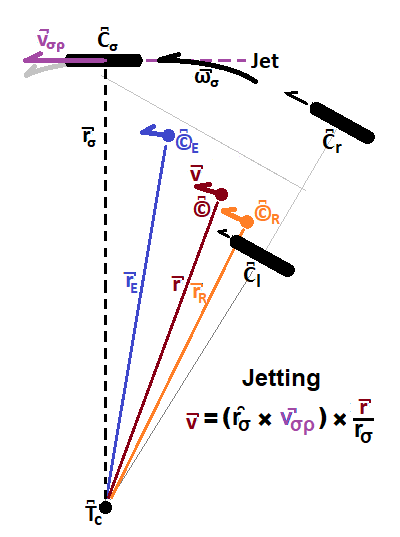
Two main actors appear in the Jet snap-shot diagram, Figure 6: the Extended-Trikke with center of mass at ©͆E (blue dot) and the reduced rider with center of mass at ©͆R (orange dot). In this section, "Trikke" means Extended-Trikke and "rider" means reduced rider. While purely jetting, the rider's position relative to the Trikke is stationary. Jetting is all about adding rotation ω̚σ through the stem contact point C͆σ (center of guide-wheel) around the turn-center T͆c (black dot). The result of the rider's rotation action on the Trikke is linear motion v̚ (brown ray) along the TRS path unit ray ρ̑ (parallel to v̚). The effect of the input rotation ω̚σ (thick black arrow) depends on the guide-wheel contact turn-radius r̚σ (black dashes), and the specifics of the rider's technique that determines ©͆ and therefore r̚.
To avoid constructing a model of how the rider generates ω̚σ (a future paper) consider the rider's jet input to be the locally generated linear velocity produced at the guide-wheel contact v̚σρ (purple ray). From this linear velocity, the stem contact rotation ω̚σ derives. All parts of the Trikke rotate around the turn-center at this angular velocity at the instant in time framed by the diagram. Its linear component at the TRS center of mass (brown dot) derives according to the simple geometry of the diagram. Note the Trikke's moment of inertia need not be accounted for by this use of v̚σρ. Inertial resistance, the various wheel frictions and air resistance are assumed to have been overcome by the rider's effort in establishing this linear velocity.
Once ω̚σ is known, the turn-ray from the TRS center of mass r̚ (thin brown line) factors into the velocity v̚ (thick brown ray) at the TRS center of mass ©͆ along the path ρ̑ (parallel to v̚). Like every part of the Trikke, ©͆ is constrained to move in orbit of the instantaneous turn-center T͆c with rotation ω̚σ due to the constraining power of the wheels at their contact points C͆σ, C͆l and C͆r. The magnitude of v̚σρ is simply related to v by r/rσ.
Jetting can be reversed when a rotation ω̚σ about the turn-center occurs in the opposite direction. The effects are clearly opposite those of a corresponding forward rotation. Though the "pulls" of the following mechanisms can produce such rotations, they are typically over-powered by the global rotation of the Trikke or nixed by the rider's technique. When there is an effect, it reduces the global rotation about the turn-center.
Pushing and Pulling a Trikke
As mentioned above, direct pushing and pulling on a vehicle traveling a straight line does little to promote acceleration. In some cases, a quick impulse can exceed natural frequency processes (as in starting a swing) or friction work functions (hopping a chair forward while seated) to cause system center of mass motion. Such were not found as sustainable mechanisms for riding a Trikke. These diagrams show that pushing and pulling a Trikke produce system acceleration moderated by the inertial properties and geometry of the actors. Computer model runs show that direct-push can contribute a significant momentum change in a carving cycle.
There are two actors (see Figure 2), the Extended-Trikke which moves at the guide-wheel contact point C͆σ and the reduced rider with center of mass at ©͆R. They are treated as semi-independent entities constrained to their arched paths and subject to the conservation of momentum. Combined, these produce a TRS center of mass displacement or "step". Analysis of this mechanism is almost as simple as jetting.
Direct-Push Path Action Vectors
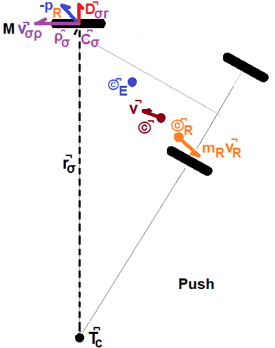
Movement of the rider generates a linear velocity v̚R (orange ray in Figure 8). This produces a momentum proportional to the rider's mass mR that must be balanced by the amount transferred via the guide-wheel path ρ̑σ to the Trikke and rider plus that lost radially along ȓσ to friction and gained Earth momentum. Though it will ultimately move, ©͆E (blue dot) is not the receiving focus of the rider's action. Rather, the guide-wheel contact point C͆σ receives the separation action via a sequence of linkages during this snap-shot of time. Speed that would be imparted to ©͆E manifests at C͆σ because it is free to move, but it is constrained to align with its path direction unit vector, ρ̑σ (parallel to v̚σρ).
The force of the push acts equal and opposite to both the Extended-Trikke and rider - Newton's Third Law. However, the force is not typically aligned with the guide-wheel path. Therefore only its component aligned with the path (orbital) affects it, the rest (radial) becomes side-ways drag on the wheels. Stated in terms of momentum, before separation local momentum is zero. After the separation stops, the sum of momenta is still zero. But because the Extended-Trikke is constrained to movement in orbit around T͆c (black dot), it can only receive angular momentum. The Rider is free to move anywhere during the separation. This means the two actors transfer equal and opposite angular momenta by conservation of that quantity, but the rider's linear - off orbit - momentum is dumped radially into friction at the wheels. This radial momentum causes the Earth to gain an opposite amount: first transferring some to molecules touching the wheels which alter physically, perhaps some chemically, and alter speed and rotation; secondly, any amount left over to the change the rotation of the Earth itself. Treating as a force or momentum transfer gives the same result when split into orbital and radial components.
This reasoning also shows that if the push (or pull) action v̚R lies along ȓσ, no rotation is produced but the rider moves backward (or forward) at speed vR with no effect on the TRS velocity. On the other extreme, when v̚R aligns with the path ρ̑σ, only rotation is produced which to first order has the same solution as the conservation of linear momentum with no movement of the TRS center of mass at all during the separation event. What happens between these extremes, is examined next.
When a force acts at an angle to a constrained path, it splits into perpendicular components, one along the path and one across the path. Their vector sum must add up to the original force. Such components are found by dotting the force vector by each path. In the push/pull analysis, the force along the path provides thrust for the orbital momentum while the force across the path increases the path-constraint drag at the wheel. For a real wheel, this sideways force may cause the wheel to slip to the outside of the turn on a push and to the inside on a pull. The model assumes no slip at all.
Finding the change in guide-wheel velocity due to a push or pull is straight-forward. See the result in the summary below.
The rider can only recoil backward so much before ©͆ travels behind the trailing wheel axles. At that point, the Trikke ride may end abruptly with a wheelie. Combined with the drive cycle time, this naturally limits how much push a rider can generate. In normal operation, the rider stops rearward movement to "join" the Extended-Trikke inelastically where the two bodies now behave as if stuck together. All the local momentum of the rider returns to the system stopping further ©͆ push-motion. What motion has occurred remains as a "step" in the displacement of the guide-wheel contact.
Direct-Pull Path Action Vectors
When the jetting action is reversed by a pull, the change in guide-wheel velocity also reverses. If the pull can be avoided, so can its displacement loss. When a turn and pull follows a push, the step achieved by the push is where the turn begins grabbing the pavement. The decelerating step of the pull can be "paid" for by the rider's jetting input. However, good riding techniques exist that avoid or greatly reduce a position "reset" pull due to the synergies of Trikke geometry.
Unconstrained, this mechanism converts pull into deceleration around the turn-radius of the guide-wheel which is the core of the jet mechanism. The Jetting input action is the increment in rear-ward linear velocity of rotation induced by the pull. ©͆R and ©͆E can only move until the rider ends the pull or bumps into the handlebars. They stop inelastically as the arms and legs of the rider hold mR and mE in place at the proximal extreme position. At that moment the masses "fuse", momentarily accelerating to the global TRS rotation.
Caster-Pull/Push Path Actions
So far, the motive mechanisms discussed are directly rider controlled. Castering is an indirect rider effort mediated by physical linkages from the guide-wheel contact point to the yoke, the Yoke-Lever and the Trailer-Lever. Computer model runs suggest caster-pull/push contributions at best attain about a seventh of the momentum that direct-push produces in a normal carving cycle. For the Trikke, it is a relatively complex, but small effect.
Caster-Pull is described first then Caster-Push, which is the mechanism with opposite x-axis orientation; both produce momentum primarily across the guide-wheel path. In a drive-cycle, the natural steering sequence invokes Caster-Pull followed by Push. A little jet action results as the Caster-Push transfers the Pull momentum from the trailer to the Trikke and rider. These actors are different from those involved in direct-push/pull. In castering, they are the Extended-Stem and Trailer of Figure 3.
Caster-Pull Action Vectors
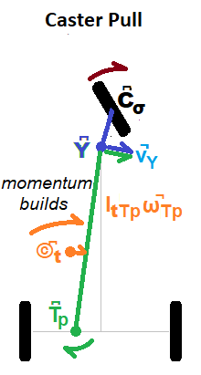
A turn toward the center (brown arrow in Figure 10) pulls the yoke Y͆ into the turn via the Yoke-Lever (blue line) and up to several centimeters closer to the contact point C͆σ, especially with cambering. It also raises the yoke vertically up to five-centimeters. This in turn cranks the Trailer-Lever (green line) into the turn and brings it closer to the twisting guide-wheel contact point C͆σ. This contraction mostly slows the guide-wheel rotation, but it also rotates the trailer's center of mass ©͆t slightly into the turn and forward.
As the yoke rises, the trailer center of mass is drawn closer to the yoke by triangle geometry; the base decreases as the hypotenuse tips up; a Direct-Push. This contraction amounts to less than one-percent of the base-distance from yoke to transom T͆p. It is ignored in this simple model.
What cannot be ignored is the yoke being pulled into the turn which causes the trailer to gain angular momentum around the transom. This momentum does not come from nor detract from the TRS. Driven by the rider, both the stem's local increase in angular momentum around the contact point and the trailer's are generated by turning the handlebars. Rotation of the Trailer-Lever (green arrow) moves the trailer's center of mass ©͆t into the turn accounting for most of the momentum change. Note the trailer rotates around a point between the rear wheels closer to the one with greater instantaneous friction - the transom point. This angular momentum continues to build independent of the TRS until the stem turns past the forward direction and the turn slows.
Caster-Push Path Action Vectors
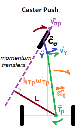
Continuing the turn past center, as illustrated in Figure 11, pushes the guide-wheel contact point C͆σ and yoke Y͆ apart via the Yoke-Lever (blue line) and dips the yoke lower. The tire increases its spin. Especially when the tires have a tread pattern, the rider can hear the guide-wheel slow down with the pull, then speed up with the push. This action continues to crank the Trailer-Lever (green line) around the transom T͆p and further into the turn, pushing it slightly backward as the yoke descends. This very slight Direct-Push is ignored in this model.
The trailer's angular momentum may continue to build as the trailer's center of mass ©͆t continues to move. As the turn completes, the movement begins to slow down and its momentum is released through a jet (v̚σρ) down the guide-wheel path in a perfectly inelastic collision. If the rider's center of mass approaches the handlebars, trailer momentum increases but the handlebars become more difficult to turn. When poised further back near the transom, trailer momentum contributes little, but turning is easy. The rider is also closer to and more aligned with the Trikke's minimum rotational inertia axis. Notice the lever-arm L in Figure 11. The longer it is, the more momentum feeds into the jet. When the wheel is straight, L has zero-length and no momentum is transferred. In summary, as the guide-wheel turns out, the lever-arm lengthens and momentum "bleeds" into the jet until the steering rotation stops.
Conclusions
Adding angular momentum, jet, to a turning system predictably makes it turn faster! Utilizing a virtual lever to transduce that jet into system velocity makes riding a Trikke mysteriously magic for many. Direct push, typically a more intuitive mechanism, in a Trikke performs in a manner foreign to most people's experience producing cyclic steps or no effect at all. Rotation on a Platform helps illustrate wind-up in castering and jet and their subsequent release.
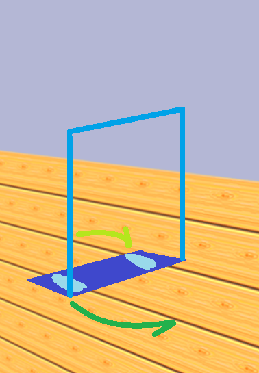
Stripping the TRS to first-order components and mechanisms exposes a simple toy many of us made as children when beckoned by a freshly waxed floor or new carpet. A piece of corrugated cardboard or carpet remnant (for the waxed floor) sufficed to slide across the floor. Inevitably, we began "walking" it across. Sliding it from side-to-side by rotating around the "planted" foot as much as possible. To this effect, hips swung to power the moving foot around. Then the other way around moving the other foot, each time shifting the weight to the planted foot. This is essentially a Trikke with no stem and no wheels, the Trikke arms reduced topologically to a rectangle of stiff, bottom-slick material as illustrated in Figure 13. As children, we instinctively understood alternate-hemijetting.
Conceptually, to add push and pull, anchor a light vertical frame to the slick rectangle. Shoving it forward and jetting a foot to separate the centers of mass (apparatus and child) causes it to slide. Suppose one kept balanced enough, the friction work function could be overcome to reset to the initial state without sliding back. Ready to push again. Though the behavior is similar to a Trikke, the reason the step is "kept" is not the same. The Trikke keeps it mainly because the rider can use the Trikke's geometry to avoid the pull.
Note this action is not skiing and it is subtly different from skating; it's "jetting"!
This look at Trikke physics does not include how the rider coordinates jet, push and caster. Each action must be coordinated and can be separately emphasized in rich and varied rides. An experienced rider can also produce a type of carving resonance. Quick cambering with the handlebars acts to restore the central stem position while jetting with both feet together to swing the trailer into the guide-wheel path against the stem's vertical rotational inertia. It is a tangible coordination between the two that feels like something children perform on a swing. Remember executing similar motions, hands grasping the chains while standing on a playground swing to achieve resonance against gravity? When quick enough, this type of resonance can help a rider maintain speed against the resistance of wind and slope or provide a fun, alternate way to ride.
Appendix A: Mathematical Derivations and Some Physics
Rotation on a Platform
Vector Decomposition
Cross Product Inverse
Lever-Arm
Mechanical Advantage
Appendix B: Model Derivations
Jetting Path Action Vectors
Direct Push-Pull Path Action Vectors
Caster Pull-Push Path Action Vectors
Trikke EOM
Glossary
Camber, cambering Wheel tilt angle from vertical rotated around a wheel's forward path direction. Tilting a Trikke's steering column serving as the Camber-Lever to the left or right side creates a nearly equivalent vertical tilt in all three wheels. Foot-deck tops also angle synergistically to increase grip in a turn. For Trikkes, cambering generally refers to tilting the steering column from side-to-side coordinated with steering. Cambering enhances the effects of carving and castering.
Camber-Lever A second-class lever of the stem with fulcrum on the road and action from cambering that moves the yoke. It also interacts with the two levers involved in castering.
Camber thrust When a cambered wheel rotates, tread-particle elliptical trajectories are constrained to run straight when contacting the ground. This asymmetry causes a change in their momentum (a force) at right angles to the inside of the camber angle. This force and increasing change in camber pull the wheels into the turn avoiding dangerous wheel slips to the outside.
Carve, carving Most dictionaries don't define a sports sense of this word! [sportsdefinitions.com] does for skiing and skateboarding, basically a turn accomplished by leaning to the side and digging an edge or wheel into the path. In the case of "carving vehicles" or "CV"s, carving is a transfer of momentum from the rider to the vehicle synergistically constrained by ground forces on the wheels. The Trikke seems best engineered to claim this action as a primary form of locomotion. This motion mechanism provides action to the guide-wheel contact point around the Turn-Lever.
Caster, castering Most dictionaries don't define a sense of this word as a verb! Here, it is defined as a form of locomotion. To caster is to move by quickly turning a wheel with positive caster and positive trail back and forth to produce forward motion. The offset contact patch causes the vehicle frame head or yoke to move sideways a couple of inches pulling part of the vehicle's trailer mass into the turn. Impulse created by this motion in the direction of the drive wheel path first pulls, then pushes on the vehicle's stem assembly. It is the sideways rotation not the stem pull or push that creates a small jetting impulse. This appears to be the primary means of locomotion for the [EzyRoller], [Flicker], [PlasmaCar] and Wiggle Ride-On Car by Lil' Rider (no web presence) rider toys and one of the modes for a Trikke. Two levers mechanize this motion: the Yoke-Lever and the Trailer-Lever.
Caster angle - positive, negative The angle a steering column makes with the road. It is positive when the angle slopes up toward the back of a vehicle. It is negative otherwise.
Caster pull When the handlebars of a Trikke are turned and tilted quickly toward the center, the geometry of the steering mechanism and constraints on wheel motion, throws the yoke into the turn up to a few inches and pulls the Trikke's Extended-Stem and trailer a quarter inch or so closer together in a fraction of a second. Though the rotation is small, most of the weight of the Trikke and its rider get spun around the transom. The pull generates no immediate jetting impulse. Steering resistance increases as caster pull builds local angular momentum.
Caster-push When the handlebars of a Trikke are turned and tilted quickly away from the center, the geometry of the steering mechanism and constraints on wheel motion, throws the yoke into the turn up to a few inches and pushes the Trikke's Extended-Stem and trailer a quarter inch or so apart in a fraction of a second. As the turn reaches its limit, the built up angular momentum transforms into a jetting impulse. The rider synergistically leverages this push for speed by synchronizing carving impulses with it.
Citizen scientist An individual who voluntarily contributes time, effort, and resources toward scientific research in collaboration with professional scientists or alone. These individuals don't necessarily have a formal science background. See What is citizen science? [Citizen Science].
Conservative force A force that can be expressed as the gradient of a potential. When this is possible, the work done by the force is not dependent on the path taken. A "round trip" by different paths of the same length requires the same amount of work. Gravity is a familiar conservative force.
Design Of Experiment (DoE) A type of designed experiment contrived to efficiently identify (screen for) the control factors that affect the process being studied the most (main effects). DoE can model and compare the effects of several factors against each other using Yates analysis. It attempts to optimize the differences in effects and minimize the number of trials needed to obtain them. When models are attained they have least-squared, multilinear properties subject to the confounding structure of the experimental factors. When not attained, the true process model is non-linear.
Direct-Push and Pull, slinging Intentional impulse created as the rider quickly moves his or her center of mass in the opposite direction of the handlebars. Lightening the load on the drive wheel and pushing the Trikke forward with arms and legs feels like "slinging" the Trikke forward. In order to retain the ground gained, this maneuver must be concurrent with or followed by steering, cambering or both. During the push or pull, the mechanism produces a jetting impulse; acceleration for the push, deceleration for the pull.
Dynamics Study involving variables related to the generation of an object's motion. Answers questions about how motion is produced.
Equation of motion (EOM) Application of conservation laws or principles like least action and balance of forces and torques to produce global kinematic and other equations for a system. For example, an approach due to Lagrange starts with energy conservation, equivalences between kinetic and potential to derive system velocities, then other kinematic quantities and sometimes Newton's force-based EOMs can be derived for the system. D'Alembert's principle allows various constraints on part velocities and positions to be incorporated in some EOMs. Other approaches create state-based generalized coordinates and use lie algebras to represent system functions. While many EOMs cannot be solved symbolically, they lend themselves to numerical solutions via computer simulation.
Extended-Stem The part of the TRS that is turned by the rider during castering. Composed of the stem, hands and wrists of the rider's body. Does not include body parts considered part of the trailer. In lever systems, one-third of a linkage between two moving parts can be shown to act as if stationary with respect to the closest attachment. So, one-third of a hand and arm acts as if stationary to the stem, another third to the trailer and a third acts with the arm's own momentum.
Extended-Trikke The part of the TRS that slings during carving. Composed of hands, wrists, feet, ankles and parts of the rider's body that sling with the Trikke. The part of the reduced rider's body producing the jetting and Direct-Push impulse is not part of the Extended-Trikke. In lever systems, one-third of a linkage between two moving parts can be shown to act as if stationary with respect to the closest attachment. So, one-third of a foot and lower leg acts as if stationary to the deck, another third to the rider and a third acts with the lower leg's own momentum.
GCF Global Coordinate Frame, "lab" or "observer's" frame may contain an infinite number of LCFs twisting, moving and even changing size everywhere. The Trikke-Rider System LCF is fairly well behaved inside the GCF; it has a common z-axis and doesn't change scale. Observers can see and measure the TRS as it moves and turns and can all obtain the same values. But they can't feel the accelerations of the Trikke like the rider.
Jetting, hemijet The angular component of carving. Beyond the "natural" body twist accompanying slinging, the rider extends the foot outside the turn by lowering his center of mass, leaning back and twisting the hips into the turn. This angular impulse adds angular momentum to the system via the Parallel Axis Theorem through rotation about the TRS center of mass. The word comes from an outdated skiing technique using both feet. Technically, this is "alternating hemijetting" since each foot independently executes half of a "jet" (a hemijet) in one drive-cycle. However, it is possible to jet with both feet.
Kinematics Study involving variables related to the classification and tracking of an object's movement. Answers questions about the form and characterization of motion, not how the motion is produced.
Lateral plane An imaginary plane that separates the front half of an object from its back half. Its normal is parallel to the front-to-back axis of the object.
LCF Local Coordinate Frame, inertial frame or just local frame is the rider's world where the Trikke and everything on it seems relatively stationary compared to the rest of the world. It is "inertial" because the Trikke and rider "feel" centripetal force in a turn and the accelerations of its movement. Yet the Trikke remains close to the rider. "Forward" is pretty much ahead. There is a wheel always under the left foot. Things are local and for the most part in their expected places. When the rider measures things relative to his locality in the GCF, they are usually different than the same things measure by observers in the GFC.
MA, Mechanical Advantage A ratio, percentage or number expressing the force multiplier or efficiency of a lever system. For simple levers, it is the distance of the action to the fulcrum divided by the distance of the load to the fulcrum.
Nonholonomic system (also anholonomic) In physics and mathematics a nonholonomic system is a type of system that ends up in a different state depending on the "path" it takes. In the case of the Trikke, frictional forces and some geometric constraints restricting velocity but not position prevent the system from being represented by a conservative potential function. It is "non-integrable" and not likely to have a closed-form solution.
Normal A "normal" to a plane, is a ray starting at the plane which is at right angles to every ray in the plane that starts at the intersection point. Notice that the normal cannot lie in the plane. Its unit direction is also the "direction" or "orientation" of the plane.
Parallel Axis Theorem One of two theorems by this name. Translates a moment of inertia (moi) tied to a center of mass and rotation axis to an offset but parallel axis. If the moi is expressed as a tensor with no particular rotation axis, then it translates to an arbitrary point, usually on the object. The second namesake does the same for an angular momentum vector. There is also a theorem called the "Second Parallel Axis Theorem" which is simpler to apply in some contexts.
Reduced rider About fifteen percent of the rider's body mass acts as if it is a part of the Trikke. Hands and wrists move largely in unison with respect to the handlebars. Corresponding parts of the legs act as if part of the decks on the arms of the Trikke. This "reduces" the effective mass and distribution of the rider, while increasing that of the Extended-Trikke and Extended-Stem.
Sagittal plane An imaginary plane that separates the left half of an object from its right half. Its normal is parallel to the left-right axis of the object.
Steering column, stem The controlling mechanism surrounding the steering axis. Composed of the steering column, handlebars, rider's hands and parts of his forearms (about 1/3) as well as the yoke, front wheel, axle, bearings and attachments. It is considered part of the Extended-Trikke, but is the part of the TRS not included in the trailer. It is also a lever; the Camber-Lever.
Stride A body in motion has linear and rotational (or angular) velocity. Parts of the body have different velocities depending on their distance from the rotation center. Stride is the difference between a part's velocity and the linear velocity of the whole body at its mass center. Rotational velocity can be expressed as a linear velocity, v̅, at right angles to a radius pointing from the rotation center: (v̅ = ω̅ × r̅). When the rotation center is the turn-center of the TRS, and the radius ends at a wheel, the difference between v̅ and the TRS linear velocity is that wheel's stride.
Swath As a Trikke snakes its way along, the outer edges of the wheels trace a wide ribbon-like path down the road. At terminal velocity, if one connects the outer most edges of the wavy ribbon on both sides to get a long rectangle, the width of that outlined area is the "swath" covered by the Trikke. In simpler terms, it is the width of the path covered by the Trikke. If something is within the swath of the Trikke, there's a decent chance it will be hit depending on Trikke's trajectory.
Trailer The parts of a TRS that are rotated around the transom and pulled or pushed slightly by the Trailer-Lever while castering. Consists of the parts of a Trikke other than the steering column, front drive wheel, handlebars, "handlebar-stationary" hands and parts of the forearm (about a third of it).
Trailer-Lever Caster action is applied at the yoke by the Yoke-Lever which rotates it and pulls or pushes it. The center of mass of the trailer is its load. Its fulcrum is the Transom point. The Trailer-Lever is a second-class lever and push-rod.
Transom Used to indicate the point on the line between the rear wheel contact points with the ground acting instantaneously as the Trailer-Lever fulcrum. Its position is determined by the ratio of instantaneous friction at each wheel. Thus, when the load is nearer the left wheel, the transom point, or just transom, is nearer the left wheel. For equal friction on both wheels, it is in the center of the line between contacts.
TRS Trikke-Rider System. Refers to the entirety of the physical system composed of the Trikke, all of its relevant parts and behaviors and the rider with all relevant parts and behaviors needed to complete the current investigation. Though the road, air and other parts of the environment are required to operate the system, they are not considered part of it.
Turn-Center A Trikke orbits this stationary point at a constant radius until the steering angle is changed or a wheel slips. When steering straight, the turn-center is not defined and the turn-radius is considered infinite. Jetting makes use of the turn-ray as a second-class lever acting on the system center of mass.
Turn-Lever A turn-ray is the ray from the turn-center to a point on the Trikke. When the point is the guide-wheel contact point, the ray becomes an important motive lever as all TRS motion must move the contact point around the turn-center.
Yoke Idealized point of intersection for the three structural tubes that characterize a Trikke. This genius articulation is fairly complex and precisely manufactured. It is the soul of the Trikke - if there is one. Constant motion from steering, cambering and road vibration are robustly endured, while keeping all the wheels aligned without toe-under or splaying.
Yoke-Lever Constitutes part of the castering mechanism set in motion by turning the stem. The rotation produces an action at the yoke, which is also the load. Its fulcrum is the guide-wheel contact patch. The movement of this yoke-load acts on the Trailer-Lever which rotates it and pulls or pushes it. The Yoke-Lever is a degenerate lever.
References
Patents
Control Theory in Robotics
[RoboTrikke] Sachin Chitta, Peng Cheng, E. Frazzoli, V. Kumar. "RoboTrikke: A Novel Undulatory Locomotion System". In Proc. IEEE Int. Conf. Robotics and Automation, pages 1597-1602, Barcelona, Spain, April 2005. DOI:  10.1109/ROBOT.2005.1570342.
[Roller-Racer] P. S. Krishnaprasad and D. P. Tsakiris. "Oscillations, SE(2)-Snakes and Motion Control: A Study of the Roller Racer." Technical report, Center for Dynamics and Control of Smart Structures (CDCSS), University of Maryland, College Park, 1998.
Papers
[calibrated] Michael Lastufka, "Empirical 2nd Degree Friction Model Solution" June 2020.
[simulation] Michael Lastufka, "Dynamic Model of a Trikke T78 Air" June 2020.
[behaviors] Michael Lastufka, "Survey of Simulated Trikke Behaviors" June 2020.
[magic] Michael Lastufka, "Trikke Magic: Leveraging the Invisible" June 2020.
[conservation] Michael Lastufka, "Qualitative Body-Powered Trikke Physics" November 2022.
Other
[sportsdefinitions.com] SportsDefinitions.com. http://www.sportsdefinitions.com/, 2019.
[EzyRoller] EzyRoller LLC. 22588 Scenic Loop Rd., San Antonio TX 78255 - USA. https://www.ezyroller.com/, 2019. Email: info@ezyroller.com
[Flicker] Yvolution USA Inc. 2200 Amapola Court, Suite: 201, Torrance, CA 90501 – USA. https://yvolution.com/, 2019. Email: support@yvolution.com
[PlasmaCar] PlaSmart Inc. 228-30 Colonnade Road, Nepean, Ontario K2E 7J6 - Canada. https://plasmarttoys.com/, 2019. Customer Service 1-877-289-0730 Ext. 214